 Change Base / Cap Plate weld pattern
Tool summary :
- Sets the weld pattern for columns with base plates or cap plates.
- For columns with auto base/cap plates, this Change option sets the " Weld pattern " for the auto base/cap plate.
- For columns with user base/cap plates, this Change option sets the " Weld pattern " for the user base/cap plate.
Step-by-step instructions :
1 . Do any of the following to invoke Change Base / Cap Plate weld pattern :
▸ Home > Utilities > Utility Functions > Change Options > Change Base / Cap Plate weld pattern .
▸ Change Base / Cap Plate weld pattern icon, which is pictured above. The icon can be taken from the group named ' Edit -- Change Options ' and placed on the ribbon.
▸ Change Base / Cap Plate weld pattern can also be configured to be invoked using a keyboard shortcut , the context menu , or a mode . For the lightning interface, this configuration is done using Customize Interface .
2 . A selection dialog opens. On it are listed all columns in the 3D model that have the base plates or cap plates. The column plates can be auto base/cap plates or user base/cap plates. The members are listed by their member number [num] and piecemark .
 [15] C_14 [15] C_14
[27] C_23
[34] C_41
|
|
|
|
|
|
|
You can select multiple members if you like.
|
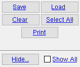
Tip: The " Print " button on this window lets you print the list of columns with column plates. Members with a " Model complete date " or whose edit windows are set to "  Lock end " do not appear on the selection list.
2a : Select any member or group of members you want changed, then press " OK ."
3 . Another selection dialog opens. It is named Select column ends to modify . On it are listed each end ( [0] or [1] ) of those columns that you selected in step 1 which has a base plate or a cap plate.
|
|
In this example, only one end of one column is listed. It is the top end [1 ] of the column whose piecemark is C_14 and whose member number is [15]. Since end 1 is the top end of the column, the column has a cap plate.
|
3a : Select the member ends that you want to modify, then press " OK ."
4 . A dialog named Change Base/Cap plate weld pattern opens.
|
Base plate weld pattern:
|
|
Automatic
|

|
|
|
|
Cap plate weld pattern:
|
|
Do not modify
|
|
|
|
  |
|
4a . Make the desired choice that you want (' Do not modify ' or ' Automatic ' or ' All around ' or ' Two faces ' or ' All faces ' or ' All faces (with seal) ') to " Base plate weld pattern " and/or " Cap plate weld pattern " then press " OK " to continue.
5 . The columns you selected in step 2a are marked for Process and Create Solids . After Process and Create Solids , you should find the following to be true.
Columns whose bottom ends ( [0 ]) you selected in step 3a should have the " Base plate weld pattern " that you selected in step 4.
Columns whose top ends ( [1 ]) you selected in step 3a should have the " Base plate weld pattern " that you selected in step 4.

